Showing posts with label Solar Charger. Show all posts

Monday, September 7, 2015

AA NiMH Ambient Solar Indoor Charger and Night Light

Indoor Ambient Solar AA NiMH Charger & Night Light

  
I had previously worked on an indoor (ambient light) solar charger for 4 AA NiMH batteries, but finally have something that does not quite work well for me. Turns out I have borrowed circuits from at least three other designs, and modified them. The goal was to work for four AA 1.2 volt NiMH 2500 mah batteries indoors under ambient light. After getting it working, I thought it would be good for a long lasting night light when I do not need to charge batteries.

I have seen other circuits for two or three AA batteries, but could not find anything that would charge four in parallel.I wanted to charge in parallel so that the charging would be done evenly, without the need to create a separate battery monitoring circuit.

The circuit also works in direct sunlight, but be warned, the batteries can get warm under direct sunlight. It works well if set near a window that gets at least a couple of hours of sun.
 
Let me see, credits should go to author P. Marian at electroschematics.com (for his 3V boost converter), mrpiiggs and Dick Cappels at cappels.org (for his 1.5 volt Solar Garden Light), and to Afrotechmods video on YouTube (for his Reverse Polarity circuits).

I plan to add a 1.2V AA low voltage indicator, but have not yet decided which circuit will be appropriate for this design.
 
  Main driver circuit for regulated output voltage:

AA NiMH Ambient Light Solar Charger Circuit #1 - The Krell Lab

Modifications included the addition of 547 transistors in an effort to increase the amps, the use of a toroid, and the use of a slightly larger (6V) solar panel.


  The main AA 1.2 volt indoor night light circuit:


AA NiMH Ambient Light Solar Indoor Night Light Circuit #2 - The Krell Lab
The above circuit connects to the charged AA battery bank. Alternatively, it can run from a 1.2 volt AA NiMH battery. I modified this one by using a toroid, using NiMH batteries (in parallel), the addition of a Light Detecting Resistor (LDR), and the use of a capacitor.


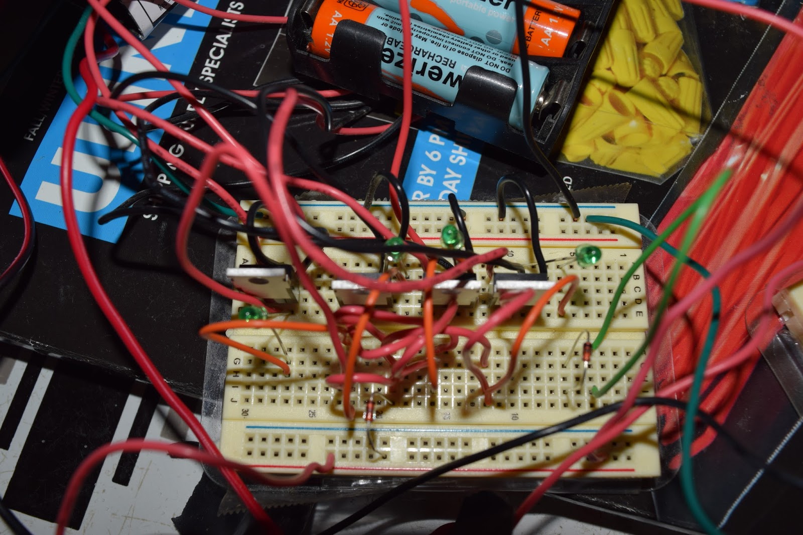
For a breadboard view, the overall circuit looks like this:

AA NiMH Ambient Solar Indoor Charger Night Light - The Krell Lab


That's a view from the kitchen table during daylight hours, the window is about 8 feet away. The white Tenergy batteries on the left were used to power the voltage meter only. The charged AA NiMH batteries are near the upper right hand corner.

The volatge regulation circuit is on the bottom left, the night light is on the right, and the polarity check circuit is on the upper left. The batteries are charged in parallel on the upper right.

The above voltage regulation circuit looks like this on the breadboard:
  
 
AA NiMH Ambient Light Solar Charge Regulation Circuit - The Krell Lab


The polarity check part of the circuit is below:

AA NiMH Reverse Polarity check circuit, the batteries are in parallel - The Krell Lab

And a view of the batteries in parallel, being charged from the reverse polarity check circuit:


AA NiMH battery bank of four, the batteries are charged in parallel - The Krell Lab

These are 2500 mah NiMH batteries.

This would be a view of the Night Light on a breadboard:

1.2 volt AA NiMH Night Light on a Breadboard - The Krell Lab

The circuit is able to run an 'Ultra Bright' or 'Super Bright' 10mm LED.
 
 Warning - Do not look directly into an 'Ultra Bright' LED.


And this would be the same night light on a perferated circuit board:

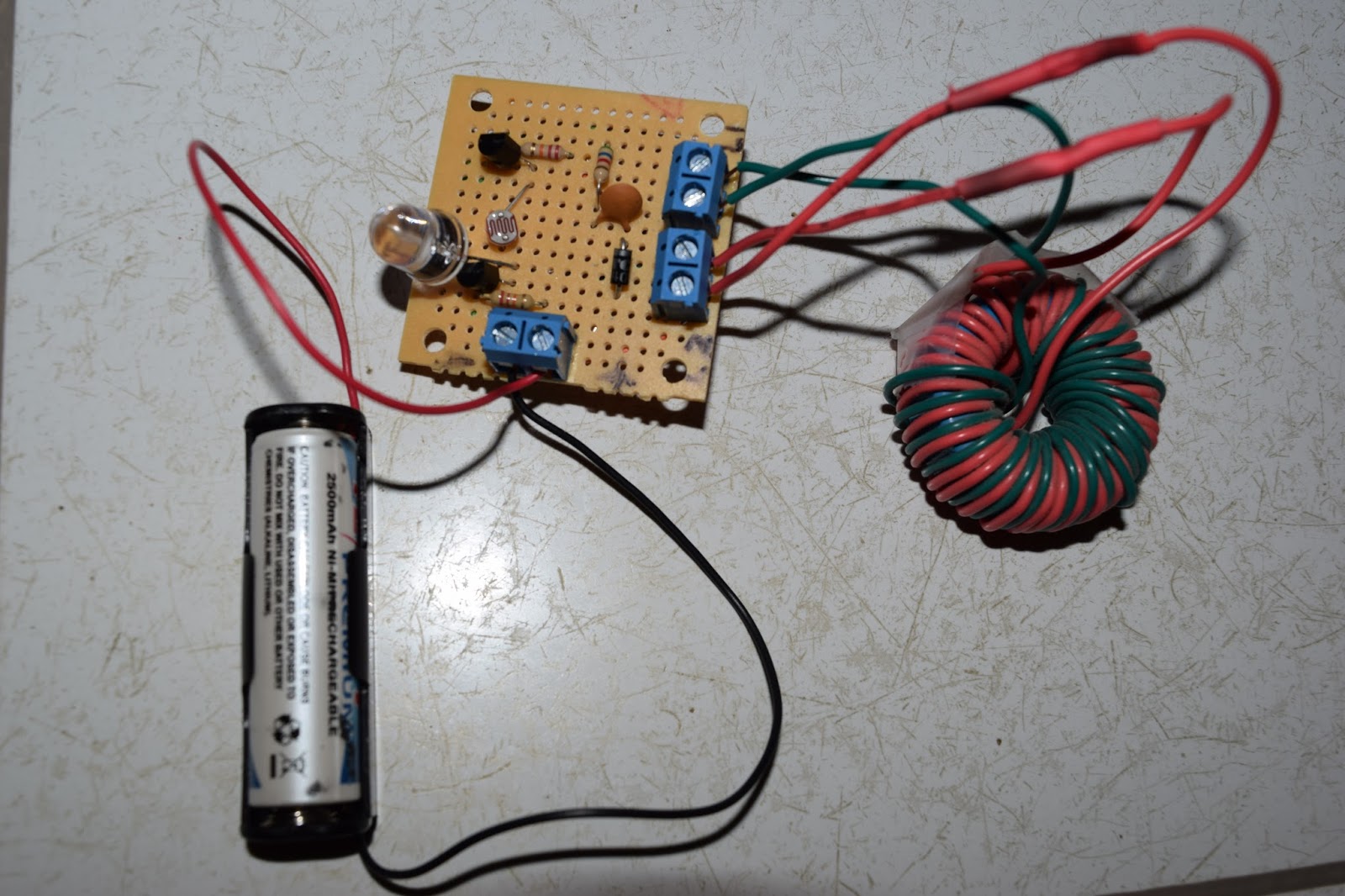
1.2 volt AA NiMH Night Light on a PerfBoard - The Krell Lab
 This version on the perf board has a toroid wound differently, but it still works. I just happened to have this toroid on hand and haven't taken the time to wind another yet.
 
In this picture, I have the windings backwards, as L1 should have the more windings. Just goes to show that it still works when the windings are backwards. However, the LED is not nearly as bright, so if you are not getting a bright light, then check the windings.

I have not tried the ferrite core, as I have no ferrite cores available.

So, there you go. If you want to charge 4 AA NiMH batteries indoors, or just run an indoor night light from rechargeable batteries (or do both), then this should work for you. 

The main problem is I see is regulating the amperage, as in using direct sunlight vs. ambient light. Which is to say, without appropriate amperage, the batteries will not last long under a normal load. So, what is needed next is to test for longevity. I am thinking I may test the number of coil windings and type of coil used (Joule Thief vs. Inductor) for the voltage regulation part of the system. Or, otherwise find a way to increase the current when not in direct sunlight, and keep the default current under direct sunlight.

Update 09/16/2015:

 Using one 6 volt, 1 watt panel, it does not charge properly, and does lose charge over time.
My current thinking is that the main problem is the lack of sustained current (on the order of 250 ma).

Some of the less common parts:


 Warning - Do not look directly into an 'Ultra Bright' LED.

YouTube Video:


                      AA NiMH Ambient Indoor Solar Battery Charger and Night Light
                                                      http://youtu.be/b4epGR1mRyI


Thursday, May 28, 2015

How To Build an MPPT Solar Charge Controller with Arduino


How To Build an MPPT Solar Charge Controller with Arduino

Julian Ilett has a series of 20 YouTube videos that show you how he built an MPPT solar charge controller with Arduino. Maximum Power Point Tracking (MPPT) is electronic tracking that enables the charge controller to compare the output of the panels to the battery voltage. It then figures out what is the best power that the panel can put out to charge the battery.

What that usually means that it tries to increase the charge on cloudy days (or in the mornings if your panel is not pointed to the sun) so that you can get the most from your panels.


Arduino MPPT Solar Charge Controller by Julian Ilett


 What is nice about this one is that he walks you through "How To" build the graphic display.

MPPT Solar Charger Graphic Display by Julian Ilett


There are 20 videos in Julian's video series, and they start here:


MPPT Solar Charge Controller #1 - Introduction and Voltage Measurement

http://www.youtube.com/watch?v=MSz4-cr3EJw&list=PLjzGSu1yGFjWv4KeN-7TSYeQIcicM9Ghl

At video #14, he changes the name of the series:

Arduino MPPT Solar Charge Controller #14 - Stable Current Measurements 

 http://www.youtube.com/watch?v=PqKOyRdB2RU&index=14&list=PLjzGSu1yGFjWv4KeN-7TSYeQIcicM9Ghl

 And, if you would like to see where he ended with the videos on this topic, here is #20:

Arduino MPPT Solar Charge Controller #20 - Inductor Discontinuous Mode

http://www.youtube.com/watch?v=k9UFrCIVp0Y&list=PLjzGSu1yGFjWv4KeN-7TSYeQIcicM9Ghl&index=20


Wednesday, May 13, 2015

How to Build the SolN1 Portable Solar Generator for Safety


How to Build the SolN1 Portable Solar Generator for Safety

LaserSaber came up with the idea of a light-weight mobile solar power generator with his video on YouTube.


However, the original SolN1 is missing the controller, and that controller should be compatible with LiFePO4 batteries...

Also, if you use the flat LiFePO4 batteries, you really need a Protection Circuit Module (PCM) for charging the four (flat) LiFePO4 batteries.


Here's a video from John Strabismus where he has the LiFePO4 controller and PCM:


The charge controller is needed so that you do not overcharge the battery. If you overcharge the battery, the LiFePO4 batteries tend to swell up, and can emit some dangerous fumes. In the worst case, they can even catch fire.
 
The battery management system is required because combining batteries for total power can cause a discharge at different rates per battery. This can cause problems when charging, leaving some of the battery pack undercharged, and others overcharged.

Regarding sizing of the PCM module, John Strabismus says:


"The main thing to keep in mind with your PCM choice is the size of the inverter you will be running. LaserSaber chose a 150w inverter, fully loaded it will pull close to 15amps continuous and surge a bit higher, that's why the surge rating on the PCM is higher than needed, as the inverter starts up with load it will pull more amps briefly then settle to its load draw, so the 16amp PCM matches the 150watt inverter, if you go higher like a 200 watt inverter you will be over the 16amps draw fully loaded and this will more than likely cause the PCM to shut down the load , so using a 20amp PCM for a 200watt inverter will match the components better."

So, you should remember that the PCM chosen should be based upon the power of the inverter.

You can find the PCM circuit boards on BatterySpace.com:

------------------------------------  
  - PCM for a 150 Watt inverter:
------------------------------------  
Protection Circuit Module (PCM) for 4 cells (12.8V) LiFePO4 Battery Pack at 16A limited  
Part Number: PCM-LFP12.8V16A

http://www.batteryspace.com/pcmprotectioncircuitmodulefor4cells128vlifepo4batterypackat16alimited.aspx


-------------------------------   
PCM for a 200 Watt inverter:
-------------------------------
Protection Circuit Module (PCM) for 4 cells (12.8V) LiFePO4 Battery Pack at 20A limited
Part Number: PCB-LFP12V25A


http://www.batteryspace.com/PCB-for-4-cells-12.8V-LiFePO4-Battery-Pack-at-20A-limited.aspx


or


Part Number: PCB-LFP12.8V20A
http://www.batteryspace.com/pcbprotectioncircuitmodulefor4cells128vlifepo4batterypackat20alimited.aspx

   ------------------------------------------  

The "Flat" type of LiFePO4 batteries can be found on AliExpress:
 

3.2V 20Ah A123 LiFePO4 Prismatic APP72161227 PHEV/EV/E-REV Rechargeable Battery      $33.88 each x 4
http://www.aliexpress.com/w/wholesale-a123-prismatic-lifepo4-20ah.html

3.2V 5C   20Ah
Nominal Voltage:    1.2V
Nominal Capacity:    20Ah
Size:    7x166x227mm       (.276" x 6.54" x 8.94")
Package Size:    10cm x 10cm x 5cm (3.94in x 3.94in x 1.97in)
Cell Weight:    About 496 g   (1.09 pounds ea.)
Cell Capacity (minimum, Ah):    19.6A
Charge voltage:    3.75V
Power:    Over 2,400 W/kg and 4,500 W/L
Continuous discharge rate:    5C 100A
Peak discharge rate:    20C 400A (10 seconds) 


The original SolN1 videos:

 DIY Build Session SOLN1 Portable Solar Power:
https://www.youtube.com/watch?v=7CUuqJDzo1U

 SOLN1 - Amazing all in one free energy portable solar unit:
https://www.youtube.com/watch?feature=player_embedded&v=hy9wT7Vvkdw


DIY Build Session SOLN1 Portable Solar Power
https://www.youtube.com/watch?v=7CUuqJDzo1U

SOLN1 - Amazing all in one free energy portable solar unit.
https://www.youtube.com/watch?v=hy9wT7Vvkdw


Real Time SOLN1 Making-of + Other Updates
https://www.youtube.com/watch?v=x2XwmnjnwH0

SOLN1 Version 3 - Solar made easy!
https://www.youtube.com/watch?v=7-Y5TvWpWoQ


SOLN1 Update - Testing the Mini Boostpack
https://www.youtube.com/watch?v=z0a-2Zcy-VI


Battery Free Solar! Real Time Solar - Nano BoostPack + SOLN1
https://www.youtube.com/watch?v=_io9YHKdbTw


SOLN1 25 Kit Build Video - 20Ah Version
https://www.youtube.com/watch?v=MUUwnMwRlTk

Sunday, November 9, 2014

Make a Solar AA Battery Charger by TL497 (my review)


   Make a Solar AA Battery Charger by TL497 (review)

This is a project to use a solar panel to charge a small battery, such as a NiMH battery in the 3V to 9V range, with mAH measuring between 1,000 to 2,000 mAH. It's just great to see that they have also included the PCB layout for you on this design. Something I don't see very often.


http://www.eleccircuit.com/make-solar-aa-battery-charger-by-tl497/


The TL497 integrated circuit is a fixed-on-time variable-frequency switching-voltage-regulator control circuit. It features frequency control and current limit sensing, among other things.
 

Make a Solar AA Battery Charger by TL497 from Electronic Projects Circuits


First things first, I have to point out that I am not using their circuit as designed.

The circuit calls for a 5V 100 mA solar panel, and I only have a 6V, 1 watt solar panel available. Secondly, I am trying to use it to charge 4 AA NiMH batteries, rated 2500 mAH, which is also not to specifications. Third, it calls for a 40 uH inductor. I don't happen to have a collection of inductors, but I do have a few toroids available.

Be aware that I am not using this circuit as designed, so your results may be different.

Even with my changes, it looks to be working for me. However, I hope to be performing more testing on this unit.

The circuit seems to work well for me using AA batteries when I cover the toroid about 4 times, or for about 90 turns of 22 guage wire.
I don't have a micro Henry meter, so I cannot specify what I have in those units at the moment.

I am testing in ambient light, such as what you might get in the shade, or when indoors.

At the moment, this one appears to perform better than the Solar Charger Circuit Project, and also appears to out-performs the 3 Volt to 9 Volt Converter (with either a 4.5V solar panel or a 6V 1 watt solar panel (that I have posted elsewhere). That is, sometimes it appears to perform better than the 3 Volt to 9 Volt Converter, sometimes not.


I will be doing more measurements, and trying to figure out the best way to test even though I don't have everything to specifications.
 

Previous Articles:

 Solar Charger Circuit Project (my review)

  3V to 9V Conerter (my review)
   
Currently testing for parallel charging, which is typically harder to do than charging in series.
You may get better results from charging in series.

I will also be looking at variations, such as number of turns on the toroid, etc.


Update Sep 7, 2015:

I have yet another AA charging circuit posted here:


Solar Charger Circuit Project (my review)


                        Solar Charger Circuit Project


Take advantage of the sunlight and use it as a power source. It can at least save on electricity prices continuing to rise, or be of help on a camping trip, or while traveling.

The Circuits Schematics Electronics blog has a schematic of simple power plant can be created and used to fill your motorcycle battery, your ebike battery, or for emergency lights:


     http://circuitschematicelectronics.blogspot.com/2012/06/solar-charger-circuit-project.html


The circuit is designed to charge a 12 volt battery, but I wanted to see if it would simply charge 4 AA NiMH batteries (4 to 5.6 volts).

So, I went about putting it together on a breadboard.


Solar Charger Circuit Project from Circuits Schematics Electronics


I was curious if I could use this to charge 4 AA NiMH batteries, and was not disappointed.
Therefore, first off, I have to point out that I am not using their circuit as designed.

Notably, the specifications call for a 4V, 200 Amp solar panel, and a ferrite rod. I did not use either. I do not have the BY207 (Diada 5 Ampere diode). Nor am I using a 12 volt battery.

You can use a ferrite rod, possibly from an old AM radio.  I don't have a ferrite rod, but I thought I would try it with toroids, as toroids I do have.

Also, the circuit calls for a 4V, 200 Amp (total) solar panel, but I only had a spare 6 volt, 1 watt solar panel.


The specifications call for a BY207 (Diada 5 Ampere diode), which I do not have.
Instead, I tried a 1N4735A, 6.2V, 1 watt Zener diode.

 The circuit is designed to charge a 12 volt battery, but I wanted to see if it would simply charge 4 AA NiMH batteries. So, I went about putting it together on a breadboard.

However, I did get some results. At first, it did not appear to generate enough voltage or amps for my AA batteries. With a little experimentation with the number of windings on the toroid, I was able to get some decent figures for the voltage required to charge my AA batteries.

It appears to respond to an increase in the number of turns of wire on the toroid.
I have 22 guage wire available, and a blue toroid from Digi-Key. The toroid spec out as Inductance Factor of 5.46µH and Permeability of 4300.


The circuit seems to work well for AA batteries when I cover the toroid about 2 times, or for about 60 turns of 22 guage wire. I don't have a micro Henry meter, so I cannot specify what I have in those units at the moment.

Again, this is not how the circuit was designed to be used, but I was happy to see that I could modify it for this purpose.


Currently, I am testing in ambient light, such as what you might get in the shade, or when indoors. This one appears to under perform both the use of the IC 497, and also under performs the 3 Volt to 9 Volt Converter that I have posted elsewhere.


However, it is much simpler to build, it is using parts that are generally available, and again, I am not using the circuit as designed. But, I was happy to see it respond to charging AA batteries.


Previous reviews:

   Make a Solar AA Battery Charger by TL497 (my review)

  3V to 9V Converter (my review)


Currently testing for parallel charging, which is typically harder to do than charging in series.
You may get better results from charging in series.

I will be looking at variations, such as number of turns on the toroid, serial vs. parallel charging, ambient light, etc.


Update Sep 7, 2015:

I have yet another AA charging circuit posted here:


Monday, October 27, 2014

Small Solar Battery Charger

After a few attempts at different circuits, I finally got a "small" solar panel to charge my NiMH AA batteries (properly) today. I used a 4 volt, 1.5 watt solar panel from Radio Shack to charge 4 AA batteries to a total charge of 5.3 volts. 


Yep, that was 5.3 volts of charge from a 4 volt solar panel.

And, that was not even using direct sunlight for most of the day. But it did take most of the day, which is roughly the normal charge duration for a NiMH battery.

A couple of other home made circuits that I have tried did not work for one reason or another, but I'm happy to see this one work nicely for me. One required a 6 volt solar panel in order to charge 4 AA batteries, another used a buck boost, which drove up the voltage and made it looks like it charged. Only later did I discover that it had no "juice." 


There was no amperage applied to the battery (even though the battery appeared to be charged.  Turns out that I was missing the parts to drive up the amps, and my substitutes did not drive up the amperage properly. So....).

But, I had the parts for this one and tried it out. Worked nicely for me without the LM317 current regulator, but I did have the need to add diodes at the batteries. Basically, I charged the 4 AA batteries in parallel, add diodes at the batteries, and used the 4 volt solar panel as the voltage source.

Web page:

     3V to 9V DC Converters

I used this circuit of the three (edited to add in the transistor pin-outs). 


3V to 9V DC Converters, 4 transistor version


At any rate, there is no am regulator on this design (such as an LM317), but I found that the 1.5 watt solar panel only produced up to 0.09 amps during the process. So, no current regulator was used. Also, there is a need to prevent overcharging the AA batteries, and I hope to later add something that will tell the circuit to shut down (or switch over) when the targeted voltage is reached. I used voltage and amperage meters for monitoring this test.

I did try the 555 circuit on that web page with the 6 volt solar panel, but was not able to get it working for some reason.

I'd like to apply it to a 6 volt panel, just to see if a 6 volt panel would charge 6 AA NiMH batteries. Given that the circuit is designed for up to 4.5 volts, I may have the need to add on an LM7805 voltage regulator in the event that direct sunlight drives up the voltage on a 6 volt solar panel. 

Finally, it would probably be good to add the option to charge only one AA battery instead of all four. I am looking forward to testing to see how many AA batteries I can charge with a small 6 volt solar panel.

Update Sep 7, 2015:

I have yet another AA charging circuit posted here: